
1101 W. Sanilac Rd. Caro, MI 48723
989.673.6690
A Tl130 Bottom Roller is a load-bearing undercarriage component, not simply a steel wheel beneath a crawler machine. It supports track-chain movement, guides alignment, and absorbs repeated impact across soil, gravel, and uneven work sites. Its condition influences tracking accuracy, vibration, fuel use, and final-drive stress. Small seal damage can become expensive quickly.
The global construction equipment market continues to expand, while equipment owners face stronger pressure to reduce downtime. Grand View Research has projected a construction equipment market compound annual growth rate of about 5.8% from 2023 to 2030. McKinsey & Company has also reported that predictive maintenance can reduce machine downtime by roughly 30% to 50%. These figures do not describe the Tl130 Bottom Roller specifically. They do show why component inspection deserves careful attention.
Quality expert W. Edwards Deming offered a useful warning: “Without data, you’re just another person with an opinion.” For a Tl130 Bottom Roller, data means checking roller diameter, flange wear, oil leakage, bearing noise, track sag, and operating hours. Measure it. Do not guess.
A practical inspection may reveal polished metal on one flange, a damp seal, or uneven wear across the roller surface. Those details can indicate misalignment, incorrect tension, poor lubrication, or a worn track chain. However, one limitation deserves honesty: replacement dimensions and fitment can vary by machine configuration. Part numbers alone may mislead. Verify the manufacturer’s specifications, serial number, mounting width, shaft size, and seal design before purchasing. This guide explains how the roller works, how it fails, and where routine maintenance can prevent an avoidable repair.
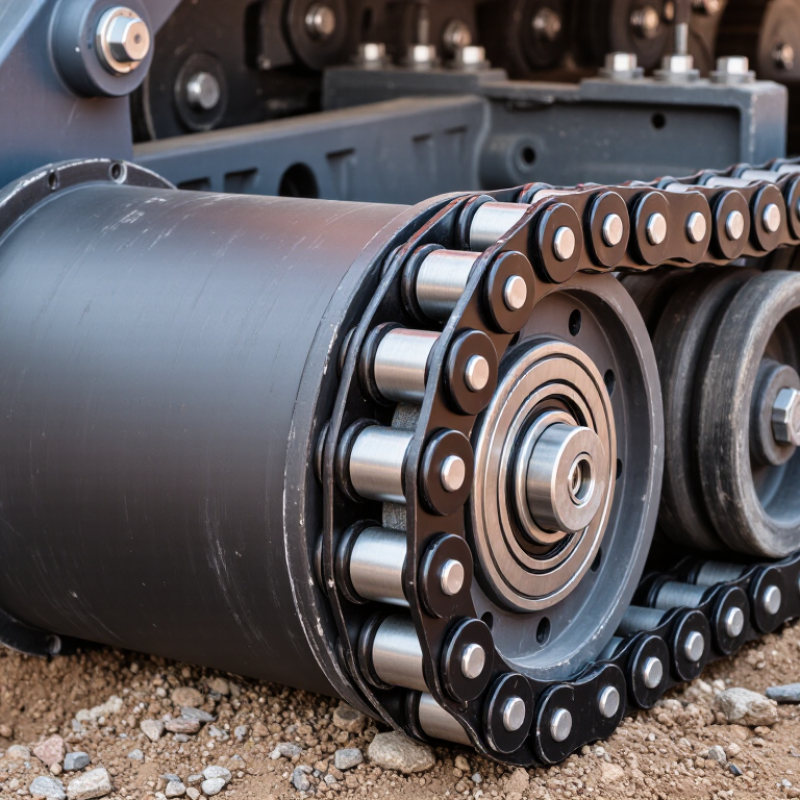
A TL130 bottom roller is a lower track roller used in a TL130 or similar 130-class undercarriage. It supports the machine’s weight between the track chain and frame. Its steel body rotates around sealed bearings while the track chain passes over it. This reduces sliding resistance and helps the track move in a controlled path. The roller is small compared with the machine, but its job is not minor.
For 130-class undercarriages, practical reference data often includes an operating weight of about 12 to 16 tonnes, track shoes around 600 to 700 millimeters wide, and roughly 7 to 9 bottom rollers on each side. Exact figures vary by configuration, working attachment, shoe pattern, and frame design. A TL130 bottom roller must match the correct shaft length, flange profile, mounting pattern, and seal arrangement. A small mismatch can cause poor alignment or accelerated chain wear.
From field inspections, uneven roller wear is often visible before serious damage occurs. One roller may show a polished edge, oil leakage, or a rough turning sound. That detail matters. However, visual inspection alone is imperfect. Mud can hide cracks, and a quiet roller may still have damaged bearings. I prefer checking roller rotation, side play, oil condition, and track tension together. The service manual remains the reliable reference, especially when 130-class data appears similar across different machines.
A TL130 bottom roller supports the lower track run and guides it beneath the machine. Its shell is the thick outer body touching the track links. It carries repeated shock loads from rocks, mud, and uneven ground. The shaft remains fixed inside the frame while the shell rotates around it. Proper alignment matters. Even slight misalignment can create uneven wear.
Inside the roller, bearings allow smooth rotation under heavy radial loads. Grease fills the bearing cavity and reduces metal-to-metal contact. Seals sit at both ends, blocking water, grit, and abrasive soil. A damaged seal often gives an early warning: dark grease, wet streaks, or side play. Small parts matter. During field inspections, technicians should check noise, temperature, leakage, and rotation resistance.
The shell and shaft commonly require controlled hardness between 40 and 55 HRC. This range helps resist wear while retaining enough toughness for impact. Excessive hardness can make a surface less forgiving under shock. Lower hardness may improve toughness but accelerate track-groove wear. Hardness should be verified with calibrated equipment and documented test points. A single reading cannot describe the entire part. I have seen rollers pass a basic check yet fail early because sealing or heat treatment was inconsistent. That is why fit, surface finish, bearing preload, and hardness must be judged together. Not flawless. Careful measurement still prevents expensive surprises.
| Component / Data Dimension | Typical Construction or Value | Function in the Bottom Roller | Inspection or Service Consideration |
|---|---|---|---|
| Roller shell | One-piece or welded steel body; outer running surface commonly hardened to approximately 40–55 HRC | Supports the track chain and transfers machine weight to the track links | Check for deep grooves, pitting, cracks, stepped wear, and excessive reduction in shell diameter |
| Track-contact profile | Machined cylindrical or slightly crowned running surface; profile depends on the matching track-chain design | Keeps the roller aligned beneath the track and distributes contact pressure | Uneven wear or a sharp shoulder can indicate misalignment, worn track guides, or incorrect tension |
| Roller shaft | Heat-treated alloy steel shaft with accurately machined bearing and seal journals | Provides the fixed mounting axis and carries radial loads from the rotating shell | Inspect journal scoring, corrosion, bending, thread damage, and wear at the seal-contact area |
| Bearings | Heavy-duty plain bushings or load-rated roller bearings, depending on the roller design | Allow the shell to rotate around the stationary shaft while carrying radial and shock loads | Excessive radial play, rough rotation, metal particles, or abnormal noise indicate internal wear |
| Floating seals | Hardened steel seal rings with elastomer O-rings or equivalent face-seal elements | Retain lubricant and prevent abrasive dirt, water, and mud from entering the roller | Oil leakage, a wet seal area, or contamination around the seal indicates possible seal or face damage |
| Internal lubricant | Oil-filled or grease-lubricated cavity, depending on the roller configuration | Reduces friction, carries heat away from bearing surfaces, and protects internal parts from corrosion | Use only the lubricant type and fill quantity specified for the particular roller design |
| End caps and retainers | Machined steel covers secured to the roller body or shaft assembly | Protect internal components and maintain the correct position of seals and bearings | Check for looseness, impact damage, distortion, and evidence of lubricant escape |
| Mounting arrangement | Rigid shaft or flanged mounting fixed to the track-frame rail; bolt pattern and shaft dimensions are application-specific | Connects the roller to the undercarriage frame and maintains its working position | Verify mounting width, shaft diameter, bolt spacing, and frame clearance before replacement |
| Surface hardness | 40–55 HRC is a common hardened range for the working shell surface | Improves resistance to abrasive wear, indentation, and deformation under track loading | Hardness should be measured on a prepared test area; the specified value may vary by manufacturer and location |
| Operating load | Carries a portion of the machine’s operating weight plus dynamic loads from travel, turning, and impacts | Guides and supports the lower track run during machine movement | Shock loading, overloaded attachments, and operation on rocky ground accelerate wear and seal damage |
| Rotation principle | The track chain moves over the stationary roller assembly, causing the shell to rotate around the shaft | Converts sliding contact into rolling contact and reduces track-frame friction | A seized roller creates drag, accelerates track wear, and may produce localized heating or shell flat spots |
| Common failure indicators | Oil leakage, seized rotation, excessive side play, abnormal noise, shell cracking, or rapid uneven wear | Signals loss of lubrication, seal failure, bearing damage, misalignment, or structural overload | Inspect with the machine safely supported; compare wear with adjacent rollers and check track tension |
A TL130 bottom roller supports the lower track chain and guides it beneath the machine. Its main job is load transfer. Machine weight moves through the frame, roller shell, track links, and ground. During travel, the roller carries a changing load rather than a steady one. Turning, slope work, and uneven soil can increase pressure on one side. Soft ground spreads the load differently. Hard ground produces sharper impacts.
Track tension also affects roller performance. Correct tension keeps the track engaged with the drive system without forcing excessive bearing load. Too much slack may cause derailment or irregular movement. Excessive tension can increase friction, heat, and wear. It sounds simple, but field conditions make it less predictable. Mud packed around the roller can change rotation resistance. A damaged seal may allow contamination into the bearing. Then the roller may feel rough, run hot, or stop rotating.
The roller should rotate smoothly while the track passes over its surface. Its bearings support radial load, while seals help protect internal lubricant. Ground pressure is not distributed perfectly. Small contact areas may carry surprisingly high forces. Technicians should inspect shell wear, oil leakage, abnormal noise, and track sag. Measuring temperature after operation can reveal friction problems early. Visual checks help, but they are not enough alone. A roller can look acceptable and still contain internal damage. Manufacturer service data remains important because “correct” tension varies with machine condition and track setup.
What Is a TL130 Bottom Roller and How Does It Work?
A TL130 bottom roller supports the crawler frame and guides the track during travel. Its steel shell contacts the track links repeatedly. This contact creates impact, sliding resistance, and local pressure. In field inspections, shiny bands often reveal uneven loading. They are useful clues.
The operating cycle begins at contact. Track weight enters the roller through the flange and bearing. Grease then protects the rolling elements and reduces metal-to-metal friction. ASTM D217 places NLGI No. 2 grease between 265 and 295 worked penetration units. That range suits many sealed undercarriage applications, but temperature and seal design still matter. Too much grease can raise churning resistance. Too little grease can accelerate wear.
Heat must leave the assembly. The roller transfers heat through its housing, shaft, and surrounding air. Mud buildup acts like insulation, so surface temperature can rise during long travel. A 2024 off-highway equipment outlook reported roughly 1.1 million construction machines sold globally in 2023, showing the scale of undercarriage demand. However, market volume does not prove service quality. ISO 281 evaluates bearing life at a 90% reliability level, yet real track shock can be harsher than laboratory assumptions. Load distribution also changes with poor track tension, worn links, or a bent frame. The overlooked detail is alignment. A roller may appear lubricated, but uneven contact can still destroy it.
What Is a TL130 Bottom Roller and How Does It Work?
A TL130 bottom roller supports the crawler track and guides its movement beneath the machine. Inside, a hardened shell rotates around a shaft, supported by bushings or bearings. Its seal retains lubricating oil and blocks mud, water, and abrasive dust. During inspection, check the roller after cleaning it thoroughly. A layer of packed soil can hide serious damage.
Wear limits should come from the machine’s service data, not guesswork. Measure the shell diameter at several points and compare both sides. Look for a sharp wear ridge, deep grooves, cracks, or uneven polishing. Small marks may be acceptable. Excessive wear can reduce track support and accelerate chain damage. The track should rotate smoothly, without grinding, wobbling, or tight spots. Listen closely.
Oil leakage needs careful judgment. A damp film may suggest an early seal problem, while fresh oil dripping onto the track requires prompt action. Check shaft end movement with a suitable lever and measure clearance using approved tools. Excessive clearance often indicates worn bushings, bearings, or a damaged shaft. Replacement timing depends on measurements, operating conditions, and repair cost. In muddy work, inspections may need to be more frequent. A practical mistake is replacing only the visibly damaged roller; neighboring rollers may already show matching wear. Record readings, photographs, and operating hours before deciding.
Generic field-service reference thresholds for wear, oil leakage, and clearance
Inspect the bottom roller when wear approaches the inspection threshold. Replacement is normally required when the tread or flange reaches the wear limit, measured clearance becomes excessive, or oil leakage changes from surface dampness to an active leak. Actual limits can vary by roller design and operating conditions, so the machine service manual should be used for final acceptance.