
1101 W. Sanilac Rd. Caro, MI 48723
989.673.6690
Selecting the right Track Drive Motor can determine whether a tracked machine climbs confidently or struggles under pressure. The choice affects traction, speed, heat, fuel use, and service life. A motor that looks powerful on paper may still perform poorly in mud, gravel, or steep terrain.
Hydraulic systems educator Daniel M. Duffy offers a useful reminder: “A hydraulic motor must be matched to the application, not selected by size alone.” That principle deserves attention. A compact excavator working beside a muddy trench needs different motor characteristics from a crawler carrier moving slowly across rock. Displacement, continuous torque, peak torque, operating pressure, reduction ratio, and braking capacity all matter. So does the final drive’s ability to dissipate heat during long travel cycles.
Start with the machine’s real working conditions. Measure loaded weight, slope angle, travel speed, ground resistance, and duty cycle. Check whether the motor includes automatic displacement control, a reliable brake, and protection against pressure spikes. Small details matter. A leaking seal can stop an entire project.
Not every recommendation will be perfect. Manufacturer charts may assume cleaner conditions than your site provides. My own practical concern is often overlooked: maintenance access. A technically excellent Track Drive Motor becomes a poor choice when technicians cannot inspect hoses, filters, or case-drain flow easily. These seven tips will help compare specifications with field reality, where performance is tested every day.
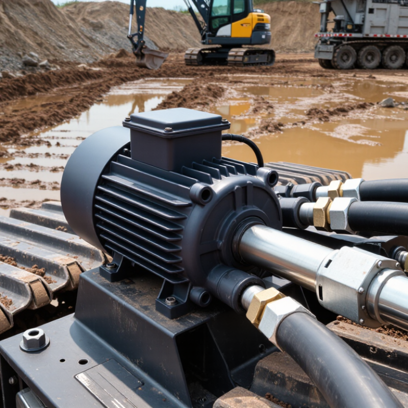
Choosing a track drive motor starts with the machine’s real workload, not its catalog appearance. Measure total mass, slope, ground resistance, and attachment forces. A compact crawler on level concrete may need modest torque. The same machine can struggle badly on wet soil or a steep ramp.
Calculate required torque from tractive force and sprocket radius. Include rolling resistance, grade force, drivetrain losses, and acceleration. Then calculate speed from target travel speed and sprocket circumference. Do not select torque alone.
A motor that delivers strong pull may move too slowly for the operator’s work pattern. I have seen projects overlook this balance.
Duty cycle controls heat. Record how long the motor moves, pauses, turns, and works under peak load. Ten minutes of continuous climbing is very different from short movements with cooling pauses. Compare those conditions with the motor’s continuous and intermittent ratings.
Add a 10–20% reserve after calculating the working requirement. This margin covers uneven ground, aging components, temperature changes, and measurement errors. More reserve is not always better. Excess capacity can increase cost, weight, and control difficulty.
A clean spreadsheet can still mislead when its input data is guessed. Test the machine with a loaded track, measure current draw, and review motor temperature after repeated cycles. Keep notes. Real soil often disagrees with laboratory assumptions.
A track drive motor should match the machine’s electrical and hydraulic systems, not just its physical mounting. Check whether the available supply is 24 V or 48 V before selecting the motor. A voltage mismatch can cause weak starting, overheating, or controller failure. Confirm the voltage under working conditions, not only from a battery label. Cables, connectors, and voltage drop also deserve attention. Small errors matter.
Hydraulic flow controls track speed, while pressure largely determines available torque. Compare the motor’s rated flow with the pump’s actual output and confirm the rated pressure exceeds the machine’s normal demand. Do not rely only on peak pressure figures. Check continuous pressure, relief-valve settings, return-line pressure, and oil temperature. Measure under load.
I once treated a pump’s maximum flow as its normal flow, which produced excessive track speed and poor control. That mistake changed how I inspect specifications.
A pressure gauge and flow meter can reveal conditions that a catalog cannot.
Test both tracks separately, especially when turning on rough ground. Cold oil may reduce movement, while hot oil can reduce efficiency and shorten component life. Leave a practical safety margin instead of operating continuously at the limits. A qualified technician should verify the final settings against the motor data sheet and machine duty cycle.
7 Tips for Choosing the Right Track Drive Motor
Compare Efficiency and Thermal Limits Under Continuous S1 Duty
A track drive motor working under continuous S1 duty never gets a real cooling break. Review its rated output, efficiency curve, and thermal limit at the same time. A motor may appear powerful on paper, yet overheat during slow travel, repeated turning, or long uphill movement. Measure under load.
Check the motor’s continuous torque, not only its peak torque. Compare electrical input with mechanical output at the operating speed you expect most often. Small efficiency losses become serious inside a sealed track frame. For example, a 5% loss can create noticeable heat during an eight-hour shift. Thermal margin matters.
Inspect the housing temperature, winding insulation class, and allowable ambient temperature. Ask for test data at full S1 load, including oil temperature and cooling conditions. I have seen calculations pass in a clean workshop but fail after mud blocked the cooling path. Real machines are less cooperative. Leave practical headroom above the published limit.
Match the motor to the reduction ratio and duty cycle. Confirm starting torque, low-speed control, braking demand, and continuous current. Check cable size and connector temperature, too. A cooling fan can help, but it also adds dust, maintenance, and another failure point. Do not accept one efficiency figure without its test speed and load. Record field temperatures with infrared readings, then compare them with internal sensor data. The disagreement may reveal a measurement mistake or a hidden hot spot.
| Tip | Selection Dimension | Recommended Target or Calculation | Typical Comparison Range | Continuous S1 Thermal Consideration | How to Verify | Priority |
|---|---|---|---|---|---|---|
| 1 | Calculate continuous tractive power | Estimate required power from rolling resistance, grade, acceleration, and travel speed: P = F × v / η Select a motor with continuous rated power above the calculated steady-state demand. | Continuous motor ratings commonly range from 1.5–30 kW for compact and medium tracked machines. | Under S1 duty, the motor must operate indefinitely at the specified load without exceeding its permissible winding temperature rise. Avoid sizing only for short-term peak force. | Use the machine mass, track friction, slope, speed, sprocket diameter, gearbox ratio, and measured current to validate the calculation. | Very High |
| 2 | Compare motor efficiency at the actual operating point | Compare efficiency at the continuous torque and speed required by the vehicle, not only at the motor's nominal rating. Higher η = lower heat generation | Industrial electric motors may provide approximately 80–95% efficiency depending on size, speed, loading, and motor technology. | Total losses are approximately: Ploss = Pout(1/η − 1) Even a small efficiency difference can create substantial additional heat during continuous operation. | Request an efficiency map or test data covering continuous torque, rated speed, low-speed operation, and field-weakening conditions. | Very High |
| 3 | Check the continuous torque-speed envelope | Confirm that the required operating point lies inside the continuous-duty region at the intended supply voltage and ambient temperature. | A typical traction motor may provide a constant-torque region up to a base speed, followed by a constant-power region at higher speed. | Low-speed operation is thermally demanding because cooling airflow may be reduced while torque-producing current remains high. A motor that can deliver peak torque briefly may not sustain the same torque under S1 duty. | Overlay the vehicle's required torque-speed curve on the motor's continuous and intermittent performance curves. | Very High |
| 4 | Evaluate thermal class and allowable temperature rise | Use the insulation thermal class, rated ambient temperature, temperature-rise limit, and any manufacturer's derating curve as a complete set. | Common insulation systems include: Class F: 155°C system limit Class H: 180°C system limit | The insulation class is not the same as the permitted operating temperature. Bearing grease, magnets, seals, sensors, and gear oil may impose lower practical limits. | Review winding temperature-rise data, embedded temperature-sensor limits, ambient-temperature assumptions, and allowable overload duration. | Very High |
| 5 | Match the cooling method to the duty cycle | Select natural cooling, fan cooling, liquid cooling, or housing conduction cooling according to continuous heat rejection requirements. | Liquid cooling generally supports higher continuous power density than natural convection, provided the coolant flow and inlet temperature are controlled. | For S1 operation, thermal equilibrium may take a long time. The cooling system must remove continuous copper, iron, mechanical, and inverter-related losses after the machine reaches steady state. | Confirm coolant flow rate, coolant temperature, radiator capacity, fan performance, mounting-surface thermal resistance, and cooling performance at low vehicle speed. | High |
| 6 | Allow for gearbox and drivetrain efficiency | Calculate motor power from the sprocket output requirement using the combined gearbox and drivetrain efficiency: Pmotor = Psprocket / ηtotal | A multi-stage reduction gearbox may have an overall efficiency of approximately 85–95% depending on gear type, ratio, lubrication, speed, and load. | Gearbox losses become heat inside the drive assembly. At continuous duty, oil temperature and bearing temperature can become limiting factors even when motor winding temperature is acceptable. | Check gearbox efficiency at the intended ratio and speed, oil viscosity, lubrication method, bearing load, and continuous housing temperature. | High |
| 7 | Verify environmental protection and control compatibility | Confirm enclosure protection, shock and vibration capability, temperature range, corrosion resistance, encoder feedback, and inverter compatibility. | Outdoor tracked equipment commonly requires an enclosure selected for dust and water exposure; the exact IP rating must match the installation and cleaning conditions. | Water ingress, blocked cooling paths, high ambient temperature, and repeated thermal cycling can reduce continuous S1 capacity even when the nameplate rating appears adequate. | Review the applicable IP rating, insulation resistance, dielectric withstand, sensor interface, overload settings, regenerative braking limits, and site test results. | High |
Engineering reference: Continuous S1 duty means operation at a constant load long enough to reach thermal equilibrium. Final motor selection should use application-specific load profiles, ambient conditions, cooling performance, gearbox losses, inverter limits, and verified test data.
Choosing the right track drive motor begins with its sealing specification. IP67 protection is not a decorative label.
According to IEC 60529:2013, an IP67 enclosure must resist dust entry and temporary immersion up to one meter for 30 minutes. This test occurs under controlled laboratory conditions. Mud, vibration, pressure washing, and temperature changes create harsher realities. During field inspections, technicians often find damage around cable glands, connector joints, and rotating shafts. These small gaps can defeat an otherwise strong enclosure.
Specify the complete sealing design, not only the IP code. Ask for validated test records, gasket materials, shaft-seal details, and connector protection. ISO 16750-3 provides useful methods for evaluating mechanical loads, including vibration and shock. The motor should also match the machine’s cleaning routine and operating environment. IP67 is not permanent. Seals age, bolts loosen, and repeated impacts may distort housings. That point is easy to underestimate.
A practical requirement might state:
“IEC 60529 IP67, tested after vibration and thermal cycling.”
Request inspection photographs and serialised test documentation. Keep the wording precise. I would also question whether immersion testing reflects real site conditions. It may not. A Track Motor working through wet clay needs more than a thirty-minute laboratory result. Look for drainage paths, corrosion-resistant fasteners, protected breathers, and accessible inspection points.Reliability often depends on these unglamorous details.
Choosing a track drive motor begins with fit, not horsepower. I inspect sprocket geometry, chain pitch, mounting holes, hydraulic flow, and case-drain limits. A motor can deliver rated torque and still fail if the reduction ratio is wrong. It happens more often than expected.
ISO 10265:2014 specifies performance requirements and test methods for track brakes on earth-moving machinery. Check whether the motor assembly supports the machine’s required travel, parking, and emergency braking functions. Do not accept a catalog claim as proof. Request test records showing brake holding force, leakage, stopping behavior, and performance under heat. The European Commission’s 2024 Safety Gate report recorded more than 4,200 product alerts across consumer and industrial categories, reinforcing one lesson: documentation matters when risk is difficult to see.
Use field data, too. The Association of Equipment Manufacturers reported that U.S. construction equipment sales remained above 200,000 units in 2023, indicating continued demand for replacement and service components. That volume increases the cost of choosing an incompatible drive. Compare measured travel speed with the manufacturer’s duty cycle, especially on slopes and soft ground. A practical test uses a loaded machine, a controlled incline, and repeated braking cycles.
Leave margin.
Check oil temperature after extended travel. Inspect brake response after the motor reaches operating temperature. My own preference is conservative sizing, although oversizing can reduce control and increase cost. The uncomfortable question is simple: can the motor stop the machine safely after wear, contamination, and operator error? If the answer is uncertain, the selection is unfinished.
Validate fit and safety by reviewing track compatibility, torque capacity, speed, braking performance, thermal margin, sealing, and serviceability before installation.
The chart uses a practical engineering screening score from 0 to 100. Brake performance and track compatibility should be verified against the machine manufacturer’s specifications and the applicable ISO 10265 braking requirements. A higher score indicates stronger suitability for selection.