How to Choose a Millimeter Wave Amplifier
Choosing a Millimeter Wave Amplifier is not simply a matter of selecting the highest frequency or output power. Start with the signal: its bandwidth, modulation, peak-to-average power ratio, and linearity requirements. Then compare operating frequency, gain, noise figure, output compression, efficiency, and stability across temperature. Check the details. A part that looks ideal on a datasheet may behave differently on your board.
RF power-amplifier expert Steve C. Cripps has written extensively about amplifier design. A concise paraphrase of his design perspective—not a verbatim quotation—is that power, efficiency, and linearity should be evaluated together. That balance matters at millimeter-wave frequencies, where a small mismatch, long interconnect, or warm enclosure can change measured performance. Look closely at package type, evaluation-board results, thermal limits, and recommended impedance conditions. Ask whether the published data matches your intended test setup.
This guide outlines a practical selection process, from defining system needs to checking specifications and validating performance. It also highlights trade-offs that are easy to overlook, including bandwidth versus gain and output power versus heat. No checklist replaces measurement. Use the shortlist to guide bench tests, and treat unexplained differences between simulated and measured results as a reason to investigate—not ignore.
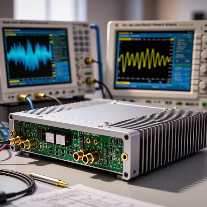
Define the Application and Required Operating Conditions
Choosing a millimeter-wave amplifier starts with the job it must perform. A receiver near a weak signal may need low noise figure and enough gain to overcome cable loss. A transmit chain may instead prioritize output power, linearity, and safe compression margin. Be specific. Record the center frequency, bandwidth, input level, and desired output level. Also note whether the signal is continuous or pulsed; duty cycle affects heating and performance.
Tips: Check the full operating band, not just the center frequency. Confirm connector type, impedance, and bias requirements before selecting a unit. Small details matter. A mismatch can reduce delivered power, while a long cable can quietly consume gain. Compare typical and worst-case figures where available, and verify test conditions.
Think about the installation, too. Enclosures, nearby components, and airflow can change the amplifier’s temperature. Include the expected ambient range and available heat sinking in your requirements. If the system operates outdoors or in a compact instrument, test it under realistic conditions rather than relying only on a bench setup. One specification may still be uncertain; flag it, then measure it before final selection.
Match Frequency Range, Bandwidth, and Gain Requirements
Start with the occupied signal, not the amplifier’s headline frequency. 3GPP TS 38.104 defines FR2-1 as 24.25–52.6 GHz, with specified channel bandwidths reaching 400 MHz. That is a wide span. An amplifier rated to 40 GHz may still lose gain or develop ripple near a band edge. Check gain flatness across the entire signal bandwidth, including filters, cables, and connectors. Measure at the intended temperature, too; a room-temperature bench result can flatter the design. A single sweep can look reassuring.
Bandwidth matters as much as center frequency. IEEE Std 802.11ad-2012 specifies 2.16 GHz channels around 60 GHz, showing why a narrowband gain figure may mislead. For gain, total the source level, passive losses, and required output. For example, a −10 dBm source, 6 dB of losses, and a +15 dBm target require at least 31 dB net gain before margin. Then check output compression and back-off for modulated peaks. Leave headroom. Excess gain can complicate stability or push later stages into compression, so verify the complete chain under realistic loading. This detail is easy to overlook.
Compare Output Power, Noise, Linearity, and Efficiency
Choosing a millimeter wave amplifier starts with the output power your system actually needs. Check power across the intended frequency band, not only at one favorable test point. At these frequencies, cable and connector losses can quietly reduce power at the antenna. Compare saturated output with the power available at your required linearity. A high headline figure may not reflect normal operation.
Tips: Leave a few decibels of power margin for losses and temperature changes. Check gain flatness across the band. Measure twice. A short cable can still matter at millimeter-wave frequencies.
Noise, linearity, and efficiency shape the rest of the choice. For weak input signals, compare noise figures under matching frequency and measurement conditions. For modulated signals, inspect compression and intermodulation performance; distortion can blur a clean-looking spectrum. Efficiency matters when heat or battery capacity is limited. Review power consumption alongside output, then consider how the amplifier will be cooled in its enclosure. Small losses add up. Bench measurements are useful, but real layouts can behave differently, so leave room to verify the design in its final setup.
How to Choose a Millimeter Wave Amplifier — Compare Output Power, Noise, Linearity, and Efficiency | Amplifier Role | Typical Output Power | Typical Noise Figure | Typical Linearity | Typical Efficiency | Best Fit | Main Trade-Off |
| Low-noise amplifier (LNA) | Output P1dB: approximately −5 to +10 dBm | Approximately 1.5–4 dB | OIP3: approximately +10 to +25 dBm | Usually below 10% PAE | Receiver front ends and weak-signal detection, where preserving sensitivity is essential. | Optimized for low added noise rather than high output power; excessive input power can cause compression or damage. |
| Driver amplifier | Output P1dB: approximately +10 to +23 dBm | Approximately 3–8 dB | OIP3: approximately +15 to +30 dBm | Approximately 10–25% PAE | Intermediate stages that provide gain and drive a following Power Amplifier. | Balances gain and linearity, but typically cannot deliver the output power of a dedicated final-stage amplifier. |
| Medium-power amplifier | Output P1dB: approximately +20 to +30 dBm | Approximately 4–9 dB | OIP3: approximately +25 to +40 dBm | Approximately 15–35% PAE | Transmit chains and test equipment that need useful power with moderate linearity and heat dissipation. | Output power, bandwidth, and linearity compete; back-off may be needed for modulated signals. |
| High-power amplifier | Saturated output power: approximately +30 to +45 dBm; higher levels may require power combining. | Approximately 5–12 dB | OIP3: approximately +30 to +45 dBm | Approximately 10–30% PAE | Transmitters, radar, and communication links where maximum transmit power is the primary requirement. | Often requires more bias power, thermal management, and linearity back-off; noise figure is generally not the key selection metric. |
| How to use these figures: These are broad, representative engineering ranges for room-temperature, narrowband millimeter-wave amplifiers around 28–39 GHz—not guaranteed specifications. Actual performance depends on frequency, bandwidth, process, matching, bias, temperature, and measurement conditions. Compare like-for-like datasheet values, especially P1dB versus saturated output power and OIP3 test conditions. |
Assess Technology, Packaging, and System Compatibility
Choosing a millimeter-wave amplifier starts with the signal chain, not a headline gain figure. Match its operating band, gain flatness, noise figure, output compression, and linearity to the system’s modulation and link budget. A unit may cover the target frequency yet still distort signal peaks or add excessive noise. Check.
Packaging can change performance at these frequencies. Compare connector or waveguide interfaces with the board layout, and inspect transition losses, flange alignment, and cable routing. A poorly matched launch can undermine an otherwise suitable amplifier. Small details matter. Also verify the housing dimensions and mounting points before designing an enclosure around the unit.
System compatibility includes power, control, heat, and measurement access. Confirm supply voltage, current demand, and any required bias sequencing; then check whether the system can remove heat from the amplifier’s baseplate. A temperature rise may shift gain or shorten reliable operating time. In a prototype, measure performance with the actual cables, adapters, and mounting hardware, not just a bare module. Datasheets cannot describe every assembly. Leave room for calibration, because real layouts and test setups are rarely perfect. Test the assembly.
Verify Reliability, Thermal Limits, and Test Results
When choosing a millimeter wave amplifier, treat reliability as something to verify, not assume. Ask for operating-life data and temperature-cycle results, then check whether tests used the same frequency range and output power you need. Look for connector inspection details, too. A loose or worn millimeter-wave connection can distort measurements before the amplifier itself shows a fault. Small details matter.
Thermal limits deserve close attention. Compare the specified case temperature with your actual mounting surface, enclosure, and airflow. A unit tested on an open bench may run hotter inside a compact instrument. Check the permitted duty cycle and output level, especially during long sweeps. Leave margin. I may be overly cautious, but a few degrees of headroom can prevent unstable gain during extended operation.
Test results should include frequency, input power, gain, noise figure, and measurement conditions. Calibration date and uncertainty matter; a clean-looking plot is not enough. Ask whether data was taken across the full band or only at selected points. Then compare it with an independent measurement, using suitable cables and adapters. Repeat the test after warm-up. If readings shift, investigate setup drift before blaming the amplifier.