
hero image

How to Choose the Right Telemecanique Sensors for Your Needs

Industrial automation depends on reliable decisions at the machine level: Is a part present? Has a guard opened? Is a cylinder at the end of its stroke? Telemecanique Sensors help answer such questions through detection and position sensing, but the right choice depends on the application. The International Federation of Robotics reported 4,281,585 industrial robots operating worldwide in 2023, a 10% increase over 2022 (World Robotics 2024). That figure reflects growing automation, not sensor sales. Still, it shows why dependable detection matters across production lines. Small details matter.

Choosing a sensor starts with the target and the task. A metal bracket, clear plastic bottle, moving conveyor, and safety gate each present different requirements. Check sensing distance, response time, mounting space, switching output, and compatibility with the control system. Then consider the real environment: oil mist, vibration, washdown, temperature changes, or nearby electrical noise can affect performance. Telemecanique Sensors offers product families for different detection needs, so compare the manufacturer’s specifications rather than relying on a product name alone. Even experienced teams can overlook a simple issue, such as a sensor being mounted too close to a moving part. That is worth reviewing. This guide explains how to match sensor type and specifications to your target, operating conditions, and installation constraints, while identifying questions to verify before purchase. When requirements remain uncertain, testing the sensor in its intended position can reveal practical problems that a specification sheet cannot.
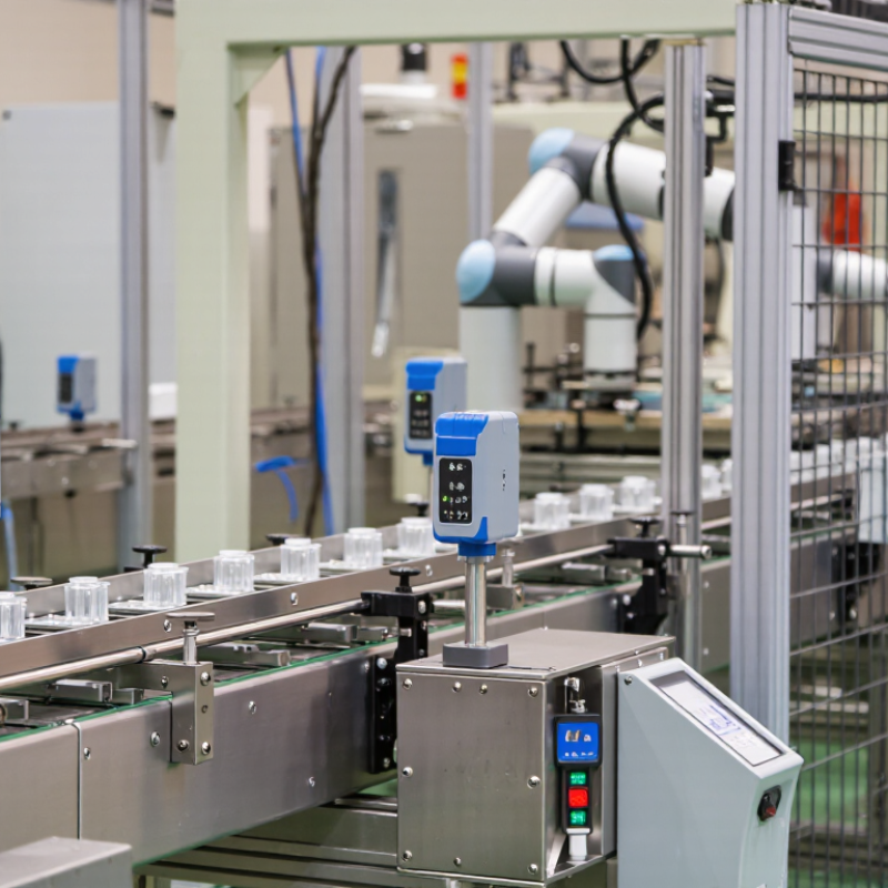
How to Choose the Right Telemecanique Sensors for Your Needs

Identify the sensing principle: inductive, capacitive, photoelectric, or ultrasonic

Inductive sensors detect metal without touching it, making them useful near moving steel parts, machine guards, or metal fixtures. Their range depends on the target material and size, so a small aluminum tab may be harder to detect than a steel plate. Check the sensing distance against the actual target, not just a catalog example. Keep nearby metal clear of the sensing face. Tight spaces can cause false triggers.

Capacitive sensors can detect nonmetallic materials, including plastic, glass, powders, and some liquids. They are flexible, but moisture or residue on the sensor face may affect results. Photoelectric sensors use a beam of light, either reflected from a target or interrupted by it. They suit longer gaps and varied materials, though dust, glare, and dark or shiny surfaces can complicate detection. Ultrasonic sensors measure reflected sound, so they can detect many colors and transparent objects. Soft materials or angled surfaces may absorb or deflect the sound. There is no perfect choice. Test with the real target, at its expected position and speed, then repeat under normal operating conditions. A quick bench test may miss vibration, buildup, or changing ambient light. That matters.

Match sensing distance and repeatability to target size and machine tolerances

A sensor’s rated sensing distance is only a starting point. Compare it with the target’s actual size, material, and approach angle. A small steel tab moving past a sensor may trigger reliably at close range, yet a smaller target or a non-ferrous metal can reduce the usable margin. Check the manufacturer’s target-material correction factors, then leave room for vibration, mounting shifts, and temperature changes. Small targets need margin.

Repeatability matters when a machine must stop, index, or reject parts within tight tolerances. IEC 60947-5-2:2019 identifies repeat accuracy and hysteresis as proximity-switch performance characteristics. These figures are measured under defined conditions; real machines add variation. For example, if a part must be detected within a 1 mm position window, a sensor with repeatability near that whole window leaves little room for fixture movement or wear. It may work during setup, then drift out of tolerance.

Tips: Measure the smallest target and the largest expected gap on the machine, not just on a drawing. Compare those values with the sensor’s rated distance and repeatability data. Test with the actual target material and at the slowest and fastest operating speeds. I would also recheck after mounting; brackets flex more than expected.

How to Choose the Right Telemecanique Sensors for Your Needs - Match sensing distance and repeatability to target size and machine tolerances
Sensing principle Typical sensing distance Typical repeatability Target and installation considerations Best fit for target size and machine tolerance
Inductive proximity About 1–15 mm, depending on sensor face size and target material Approximately 0.01–0.1 mm in common short-range applications Detects metal targets only. Standard sensing distances are generally specified using a defined mild-steel target; smaller targets and some metals, such as aluminum, can reduce the effective range. Allow for mounting and target-position variation. Good for small-to-medium metal parts and repeatable presence or position checks. Choose a sensing distance comfortably greater than the maximum operating gap, while keeping the target within the specified range.
Capacitive proximity About 1–25 mm; the usable distance depends strongly on the material and adjustment Approximately 0.02–0.2 mm in stable applications Can detect non-metallic materials as well as metals, including some liquids and powders. Moisture, deposits, target composition, and nearby objects can affect switching. Useful for larger or consistently presented non-metallic targets. For tight machine tolerances, test the actual material and environment and provide enough target area for stable switching.
Photoelectric, through-beam Roughly 0.1–20 m, depending on the equipment and environment Typically about 0.1–2 mm for a well-aligned switching application A separate emitter and receiver detect interruption of the light beam. Generally offers strong detection reliability, but requires alignment and a clear optical path. Suitable for small or fast-moving opaque targets when the beam can be positioned across the target path. Check that the target fully interrupts the beam despite expected vibration and alignment changes.
Photoelectric, diffuse or retroreflective Typically a few centimetres to several metres; strongly dependent on the method and target Often about 0.5–5 mm; surface and alignment can affect the result Diffuse detection depends on light reflected by the target, so color, finish, and angle matter. Retroreflective detection uses a reflector and can be affected by target shape and orientation. Useful when only one sensor location is practical. For small targets or narrow tolerances, verify performance with the actual target surface and the full range of operating positions.
Laser displacement or triangulation Commonly about 10–300 mm, depending on measuring range and sensor design From a few micrometres to around 0.1 mm, depending on range, surface, and model Measures position or distance rather than only detecting presence. Dark, shiny, transparent, or angled surfaces can reduce measurement stability; mounting rigidity and vibration matter. Best for small targets, height checks, and applications with tight tolerances. Select a measurement range that covers the full part variation without sacrificing the required resolution or repeatability.
Ultrasonic Approximately 50 mm to 6 m, depending on the sensor and target Often about 1–10 mm in typical industrial applications Detects sound reflections and can work with many colors and transparent materials. Soft, angled, or irregular targets may absorb or deflect sound; air temperature can influence the measured distance. Useful for larger targets, level checks, and applications where optical sensing is unreliable. Allow a wider tolerance than for precision displacement measurement and observe the sensor’s near-zone limits.
Magnetic cylinder-position sensing Usually a short operating gap, commonly a few millimetres from the cylinder’s magnetic piston Typically around 0.1–1 mm, depending on cylinder, sensor position, and switching method Requires a compatible magnetic target, usually the magnet in a pneumatic or hydraulic cylinder piston. Mounting position and cylinder construction determine the usable detection zone. Suitable for confirming cylinder end positions when the target is built into the actuator. Check the sensor’s switching zone against the required stopping or confirmation tolerance.
Planning note: These are indicative ranges for comparing sensing principles, not guaranteed specifications. Actual sensing distance and repeatability vary by device, target dimensions and material, mounting, temperature, contamination, and setup. Confirm the selected device’s technical data and test it under real operating conditions.

Check IEC 60947-5-2 ratings, supply voltage, output type, and switching frequency

Choosing a proximity sensor starts with the machine, not the catalog. Check that its IEC 60947-5-2 ratings match the intended sensing role and installation conditions. This standard covers proximity switches, but it does not replace checking the full product data sheet. Look for the rated operating distance, enclosure protection, and permitted ambient temperature. A sensor mounted beside a warm motor may behave differently from one tested on a cool bench. Small details matter.

Supply voltage is another practical filter. Confirm the machine’s available voltage and whether the sensor accepts AC, DC, or both. Then match the output type to the controller input: PNP and NPN are not interchangeable in every setup. Check whether the output is normally open or normally closed, and note its load-current limit. Switching frequency matters too. A fast conveyor may need a sensor that can respond to closely spaced targets without missing pulses. Test it at actual operating speed. It is easy to overlook.

One detail can still be uncertain: target material, alignment, and wiring may affect real performance. Leave a little margin rather than selecting a sensor at its limits. A quick trial can reveal issues that specifications alone cannot.

How to Choose the Right Proximity Sensor

Compare representative switching frequencies, then check each sensor’s IEC 60947-5-2 ratings, supply voltage, and output type against your application. The values below are generic examples, not guaranteed limits or values specified by the standard.

Sensor technology Common supply example Common output example Charted frequency
Inductive 10–30 V DC PNP or NPN transistor output 1,000 Hz
Capacitive 10–30 V DC PNP or NPN transistor output 100 Hz
Photoelectric 10–30 V DC PNP or NPN transistor output 500 Hz
Ultrasonic 10–30 V DC PNP or NPN transistor output 20 Hz

Supply voltage, output configuration, and switching frequency vary by model; 10–30 V DC and PNP/NPN are common examples, not universal specifications. IEC 60947-5-2 does not provide one universal rating for every sensor. Confirm the exact rated operational voltage, output type, switching frequency, and applicable IEC conformity information in the product datasheet. Select a switching frequency that supports the required machine cycle rate.

Select enclosure protection: IEC 60529 IP67 includes a 1 m, 30-minute immersion test

When selecting an industrial sensor, check the complete IP rating, not just “waterproof” wording. Under IEC 60529, IP67 combines dust-tight protection with an IPX7 immersion test: typically 1 metre of water for 30 minutes. The standard defines test conditions; it does not certify every installation scenario. Check the sensor’s cable entry, connector, seals, and mounting position too. Small details matter.

A useful distinction. IPX7 does not automatically mean resistance to high-pressure washdown, hot water, chemicals, or repeated immersion. IEC 60529’s test data describes a controlled laboratory exposure, not every factory’s cleaning routine. If a sensor sits near a floor drain, water may pool deeper than expected. If operators spray equipment directly, an IP67 rating alone may be insufficient. Compare the real exposure with the manufacturer’s test documentation, and confirm whether the rating applies with the chosen connector attached. This step can feel fussy. It is still worth doing. I would also review seals after installation; a damaged cable or overtightened fitting can undermine the protection the rating suggests.

Verify response time, operating temperature, and safety ratings against machine needs

When choosing an industrial sensor, compare its response time with the machine’s stopping distance, not just the catalog figure. At a line speed of 0.5 metres per second, a 20-millisecond delay allows the target to travel 10 millimetres before the signal changes. Add controller and brake delays, then check the measured stop distance under realistic load. Small delays matter. A fast sensor cannot compensate for a slow safety circuit.

Check the full operating-temperature range, including the sensor face and cable entry. A station near a washdown area, hot motor, or cold loading bay may experience condensation or temperature swings that affect reliability. Confirm the specified range covers actual conditions, with margin for seasonal extremes. ILO’s 2023 global estimates report 2.93 million work-related deaths and 395 million non-fatal work injuries annually. That scale makes careful safeguarding decisions essential, but a sensor rating alone does not make a machine safe.

Match the required safety performance level or integrity level to the machine’s risk assessment and safety-system design. Verify that the sensor, logic device, wiring, and final switching elements support the required level together. Standards such as ISO 13849-1 and IEC 61508 provide relevant frameworks. It is easy to focus on the number printed on a datasheet. Check installation, diagnostics, and maintenance requirements too; these details are less tidy, but they matter in service.