
hero image

How to Choose the Right Electrical Relays?

Choosing the right relay begins with the actual job it must perform. A compact relay switching a control signal faces different demands from one driving a motor, heater, or lighting circuit. Check the load’s voltage, steady current, inrush current, switching frequency, and expected service life. Then consider the coil voltage, contact arrangement, insulation requirements, mounting space, and operating environment. A relay that fits the socket may still be wrong for the load.

For Relays Electrical selection, ratings deserve careful attention. An AC rating does not automatically apply to DC, and resistive-load ratings may not suit inductive equipment. Inspect the datasheet for the relevant load category, electrical life, and coil power. Picture a relay inside a warm control cabinet, switching a motor several times each hour. Heat and frequent arcing can shorten contact life. Small details matter.

A practical rule for relay application engineers is: “Match the relay to the load’s real switching conditions, not just its nominal current.” This is an editorial design principle, not a quotation attributed to a named expert. If a project needs a sourced expert quotation, verify one against a reliable publication or manufacturer document before using it. Selection is rarely perfect from a single specification sheet; testing under representative conditions can reveal assumptions worth revisiting. A careful choice balances safety, performance, availability, and maintenance.
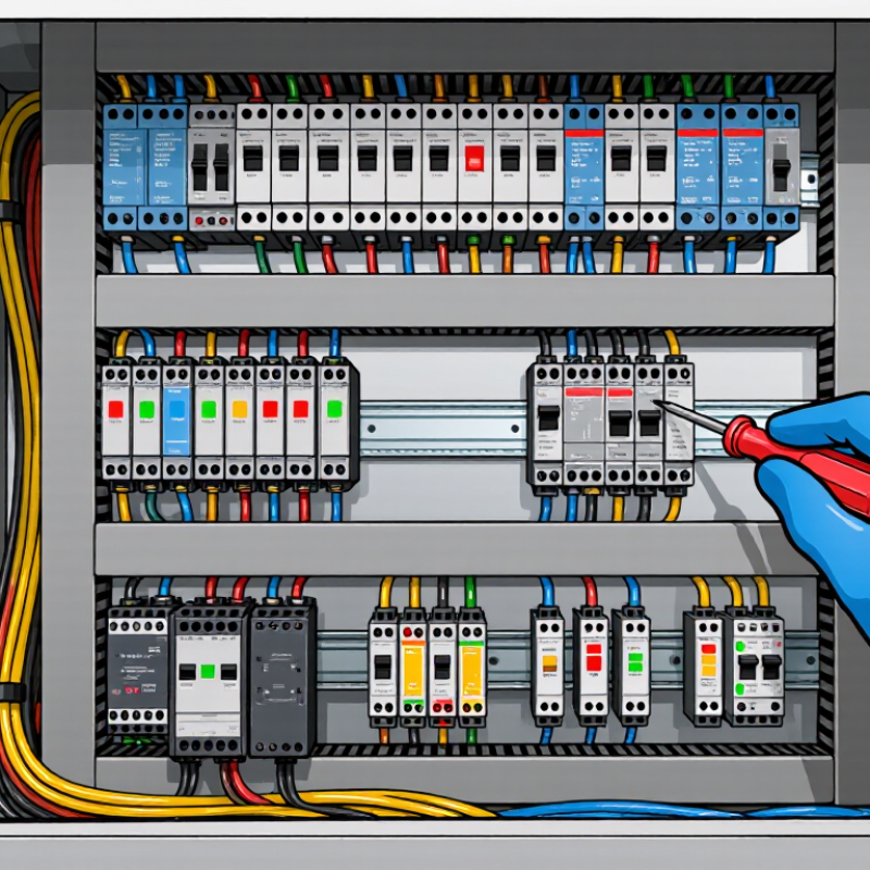
How to Choose the Right Electrical Relays?

Define the Load: 24 VDC or 230 VAC, Current, and Inrush

A relay’s coil voltage is not its load rating. A 24 VDC control circuit may switch a 230 VAC load, but only if the contacts are rated for that voltage and load type. Record the supply voltage, steady current, and load characteristics before choosing. A heater draws fairly steady current; a motor or capacitive power supply can pull a sharp startup surge. Peak matters. The U.S. Department of Energy’s Improving Motor and Drive System Performance sourcebook notes that induction-motor starting current can reach roughly five to seven times full-load current, depending on the motor. That brief surge can weld undersized contacts, even when the running current looks safe.

Tips: Check the relay’s DC and AC ratings separately; they are not interchangeable. Compare the load’s measured or specified inrush with the relay’s making-current rating and electrical endurance data. IEC 60947-4-1 defines utilization categories for contactors, including AC-3 for starting and switching off running squirrel-cage motors. For a small motor, that category is more informative than a generic resistive-load rating. Not just watts. If the datasheet omits inrush capacity, seek clarification rather than assuming a generous margin. Real installations can be messier than the rating table suggests.

Match Coil Voltage and Power to the Control Supply

Match the relay coil’s rated voltage to the control supply, and check the supply’s actual operating range. A nominal 24 V supply may dip under load or rise slightly when lightly loaded. The coil datasheet should specify its permitted voltage range. Do not assume that a relay marked 24 V will tolerate every condition around 24 V.

Small details matter. For a 24 V DC coil rated at 1.2 W, the steady current is about 50 mA. Confirm that the controller output can provide that current, with suitable margin.

Check coil power as well as voltage. AC coils may list volt-amperes, and their pickup demand can differ from their holding demand. DC coils usually list watts or current. Compare those figures with the control output’s switching capacity, not just the power supply rating.

A common oversight is voltage drop across long, thin control wiring; measure at the coil terminals if operation seems unreliable. I would also review the relay’s temperature limits and duty rating. A tidy calculation can still miss a warm enclosure.

If adding coil suppression, use a method approved for the relay and control circuit; a diode across a DC coil can slow release.

Rate Contacts by Load Category: AC-1, AC-15, DC-1, or DC-13

When choosing an electrical relay, match its contact rating to the load category, not just the largest current printed on the case.

AC-1 applies to non-inductive or slightly inductive AC loads, such as resistance heaters. AC-15 is intended for controlling AC electromagnetic loads, including contactor coils. A coil may draw modest current while holding, yet demand more during operation. That difference matters.

For DC loads, DC-1 covers non-inductive or slightly inductive circuits, while DC-13 applies to controlling DC electromagnets. DC switching can create persistent arcs, so a relay’s DC rating may differ sharply from its AC rating.

Check the specified voltage, load current, inrush, switching frequency, and electrical life in the datasheet. Small details count.

A practical check is to compare the relay category with the actual load, then confirm any coil-suppression device is compatible. Suppression can affect how quickly a coil releases. I would not assume that a relay with a higher general-purpose current rating will safely switch every load; the category and operating conditions still need review.

Compare Electrical and Mechanical Life in Switching Cycles

A relay’s mechanical life is the number of operations it can perform without an electrical load. Its electrical life measures switching under specified voltage, current, and load conditions. The figures can differ greatly. A relay rated for millions of mechanical operations may have a much lower electrical rating because arcs gradually erode its contacts.

Check how the manufacturer defines a cycle; some count one complete on-and-off sequence. Then compare the electrical-life rating with your actual load, not just its nominal current. Motors, solenoids, and other inductive loads can create harsher switching conditions than a resistive test load. Small details matter.

Estimate your switching frequency, too. Ten cycles per minute adds 14,400 cycles in a day of continuous operation. Compare that rate with the electrical-life data, while allowing for frequent starts and unusual operating conditions. A suitable suppression component may reduce contact stress, but its choice can affect circuit behavior. Read the test conditions carefully. They may not match your application perfectly, and that uncertainty deserves attention. If the load or switching pattern changes, reassess the expected service life rather than relying on the mechanical-life figure alone.

How to Choose the Right Electrical Relays? - Compare Electrical and Mechanical Life in Switching Cycles

Relay type Typical mechanical life Typical electrical life Load conditions affecting life Selection guidance
General-purpose electromechanical relay About 10 million operations is a common specified value; some designs are rated higher. Often about 100,000 to 1 million operations at a specified rated load. Rated voltage and current, switching frequency, contact material, and load type. Inductive loads can cause contact arcing. A practical choice for routine control and power switching when the load stays within the relay’s specified ratings.
Small signal electromechanical relay Commonly around 10 million to 100 million operations, depending on construction. Varies widely with the switched signal and contact rating; consult the specified electrical-life test conditions. Very low-level signals may be affected by contact contamination or minimum-load requirements; higher loads can accelerate wear. Consider for low-current signal paths. Check minimum switching load as well as maximum ratings.
Automotive electromechanical relay Often specified in the millions of operations, with the exact figure depending on the relay and test profile. Application-dependent; inrush current and inductive switching can substantially reduce contact life. Motor or lamp inrush, coil suppression, vibration, temperature, and the vehicle’s electrical environment. Use a relay rated for the actual automotive load and environment, not just the steady-state current.
Solid-state relay (SSR) No mechanical operating life: there are no moving contacts. Not usually expressed as contact switching cycles; service life depends on semiconductor stress, thermal conditions, and load. Heat dissipation, surge current, off-state leakage, load type, and switching frequency. Consider for frequent or silent switching, while checking heat-sink needs, leakage current, and surge ratings.

Note: These are broad, representative ranges—not guarantees or directly comparable test results. “Operations” generally refers to switching cycles as defined by the manufacturer. Electrical life is strongly dependent on the test load and operating conditions; check the relay’s datasheet for the exact rated load, endurance test, and cycle definition.

Check Operating Conditions and Compliance with IEC 61810-1 or UL 508

Choosing an electrical relay starts with the conditions it will actually face. Check the coil voltage range, switching load, operating frequency, and ambient temperature. Start with the load. A motor or lamp can create switching stresses that differ from a resistive test load. Also consider vibration, enclosure temperature, and expected switching cycles.

Then verify which safety standard applies to the relay and its installation. IEC 61810-1 covers electromechanical elementary relays, while UL 508 addresses industrial control equipment. They are not interchangeable stamps. Confirm the exact standard edition, product documentation, and any required approvals for the equipment’s intended market. A relay’s compliance statement does not automatically certify the complete control panel.

Compare the documented ratings with real operating conditions, not just the nominal values. For example, a relay mounted beside a warm power supply may run hotter than the surrounding room suggests. Check contact ratings for the specific load type, electrical life, insulation details, and required spacing. Leave sensible margin where conditions vary. A headline rating can feel reassuring, but it may hide awkward limits; reviewing the datasheet against the actual circuit often reveals details worth questioning.