


Choosing the right Diode Sensor begins with the measurement, not the product label. A laboratory photodiode may perform well under stable light, while an industrial sensor must survive vibration, dust, temperature changes, and electrical noise. The application defines the decision.
Start by identifying the target wavelength and expected optical power. A silicon sensor suits many visible and near-infrared measurements. InGaAs devices may be more suitable for longer infrared wavelengths. Check the active area carefully. A larger area captures more light, but it can reduce response speed and increase capacitance. Small details matter.
Then compare sensitivity, noise, response time, dynamic range, and linearity. A fast sensor is valuable for pulse detection, but it may need a stronger signal and careful circuit design. For weak signals, low noise can matter more than maximum speed. Review the manufacturer’s graphs, test conditions, and calibration information. Do not rely on a single headline specification.
Environmental conditions deserve equal attention. Imagine the sensor mounted beside a warm motor, behind a narrow optical window, with a cable running near a switching power supply. That setting may expose weaknesses hidden in a quiet laboratory. Consider shielding, connector quality, mounting space, and calibration intervals.
There is no perfect choice.
A reliable selection also includes practical testing. Compare two candidate sensors using the actual light source, distance, electronics, and enclosure. Record readings over time. Recheck them after temperature changes. This step may reveal an inconvenient truth: the cheaper device could be more stable, or the faster model may create unnecessary complexity. Careful evaluation turns specifications into dependable performance.
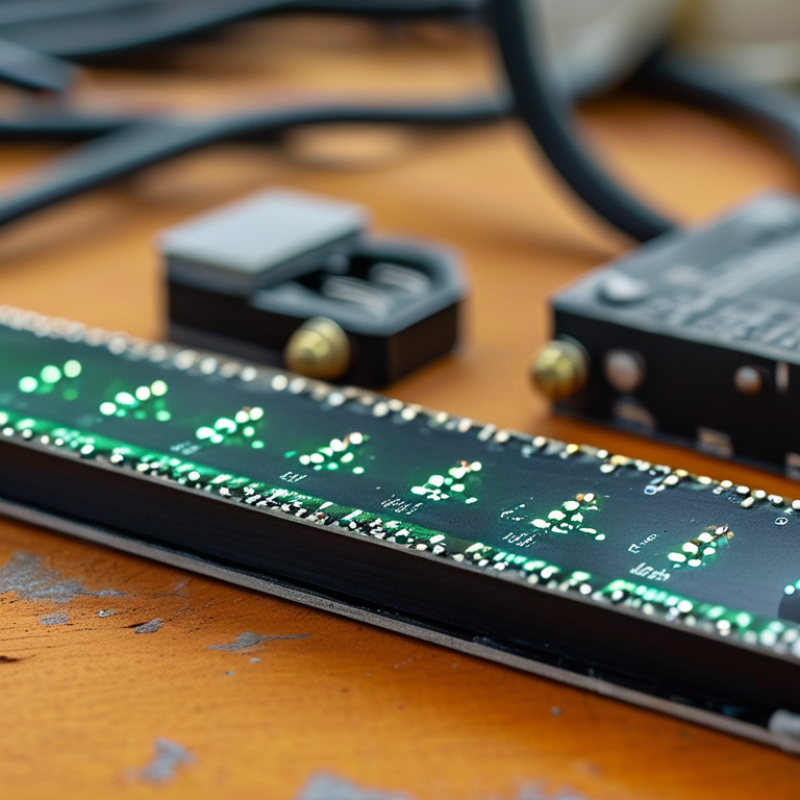
How to Choose the Right Diode Sensor for Your Application?
Define the Measurement Requirements for Your Application
Before choosing a diode sensor, describe exactly what you need to measure. Identify the target wavelength, optical power range, response speed, and required accuracy. A sensor for weak light may need high sensitivity and low noise. A sensor for fast pulses needs a short response time. Define the smallest signal that matters. Also record the highest expected input.
The measurement environment matters just as much. Check operating temperature, humidity, vibration, and available space. Consider how light reaches the sensing area. A narrow beam, scattered light, or changing alignment can affect readings. In practical testing, I have seen a suitable sensor produce unstable results because the mounting angle was ignored. That was an avoidable mistake. Detector area and signal bandwidth should match the optical setup, not just the instrument specification.
Tips: Create a requirement table before comparing sensors. Include wavelength, power limits, accuracy, speed, noise, temperature range, and output format. Leave space for uncertainty. Test the sensor with your real light source, cables, and enclosure. Laboratory results can look excellent. Field conditions are less forgiving. If the requirements are unclear, measure the application again rather than guessing. A small assumption today may become a costly redesign later.
| Application | Primary Measurement | Recommended Diode Material | Typical Wavelength Range | Typical Optical Input | Required Bandwidth | Recommended Active Area | Key Selection Requirement | Important Design Consideration |
|---|---|---|---|---|---|---|---|---|
| Fiber-optic power monitoring | Average optical power | Silicon or InGaAs | 400–1100 nm for silicon 900–1700 nm for InGaAs | -40 to +10 dBm 0.1 µW to 10 mW | DC to 1 kHz | 0.5–3 mm diameter | Low dark current and stable responsivity | Use an optical filter or fiber-coupling structure when ambient light could affect the reading. |
| High-speed pulse detection | Fast optical pulses or digital optical signals | Silicon or InGaAs PIN diode | 400–1100 nm for silicon 900–1700 nm for InGaAs | -30 to +5 dBm 1 µW to 3 mW | 10 MHz to >1 GHz | 0.1–1 mm diameter | Low junction capacitance and short rise time | Minimize cable length and amplifier input capacitance because they reduce bandwidth. |
| Visible-light intensity measurement | Illuminance or relative light level | Silicon photodiode | 400–1100 nm Best response generally in the visible range | Approximately 1 nW to 1 mW | DC to 100 Hz | 2–10 mm diameter | High linearity and a response matched to the visible spectrum | A diffuser or calibrated optical filter may be needed for uniform angular and spectral response. |
| Ultraviolet monitoring | UV intensity or UV presence | UV-enhanced silicon or wide-bandgap diode | 200–400 nm | Approximately 10 nW to 100 µW | DC to 10 kHz | 0.5–5 mm diameter | UV sensitivity with controlled visible and infrared rejection | Check window material and package transmission because ordinary glass blocks much of the UV spectrum. |
| Near-infrared reflective sensing | Object presence, distance trend, or reflected intensity | Silicon or InGaAs | 850–1100 nm for silicon 1000–1700 nm for InGaAs | 1 µW to 10 mW at the detector | 1 kHz to 100 kHz | 0.5–3 mm diameter | Adequate sensitivity at the emitter wavelength and fast response | Account for target reflectivity, working distance, incidence angle, and background illumination. |
| Long-wavelength infrared detection | Thermal radiation or mid-infrared signal | Germanium, InAs, or extended InGaAs | 1–3.5 µm, depending on material and structure | Approximately 1 µW to 1 mW | DC to 10 kHz | 0.5–5 mm diameter | Spectral response, cooling requirement, and low noise | Verify the detector’s cutoff wavelength and temperature rating for the intended operating environment. |
| Precision scientific measurement | Absolute optical power or spectral intensity | Calibrated silicon or InGaAs PIN diode | Select according to the measurement band; common ranges are 400–1100 nm and 900–1700 nm | 10 pW to 10 mW | DC to 1 kHz | 1–10 mm diameter | Known responsivity, low noise, and traceable calibration | Include temperature compensation and verify linearity over the complete optical power range. |
| Harsh industrial monitoring | Light level, flame indication, or process feedback | Silicon or UV-enhanced diode with protective package | 200–1100 nm, depending on the process | 100 nW to 10 mW | DC to 10 kHz | 0.5–5 mm diameter | Temperature range, sealing, vibration resistance, and overload tolerance | Specify the ambient temperature, humidity, dust, chemical exposure, and required ingress protection before selecting the package. |
| Selection checklist: Define the wavelength range, minimum and maximum optical input, required bandwidth, acceptable noise level, active area, linearity, operating temperature, package constraints, and calibration requirements before choosing a diode sensor. The numerical ranges above are representative engineering design ranges; final values must be verified against the selected detector specification and measurement setup. | ||||||||


